3d Geometry for Panoramic Images
Table of Contents:
- Panoramas
- Spherical Coordinate System
- Recovering Perspective Images from a Panorama
- Recovering 3D Structure from Panorama
- Datasets with Panoramas
What is a panorama?
A panoramic image offers a 360 degree view of the area. Often mapped to an image that covers a 360 degree field-of-view horizontally, but only 180 degrees vertically. This is what we are used to when seeing a map of the world, as if a globe had been flattened. It is called an “equirectangular projection” (see the Wikipedia entry for more details). In other words, it “maps meridians to vertical straight lines of constant spacing”.

Spherical Coordinate System
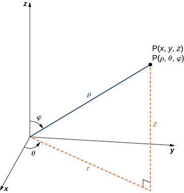
In the spherical coordinate system, we use an ordered triple to describe the location of a point in space. In this case, the triple \((\rho,\theta,\varphi)\) describes one distance and two angles (See Strang and Herman).
If \(\mathbf{P}=(x,y,z)\) is a point in space, and the x-y axes form the ground plane, and the z-axis points upwards, then:
- \(\rho\) is the distance between \(\mathbf{P}\) and the origin
- \(\theta\) is the angle component of a polar coordinate in the x-y plane
- \(\varphi\) is the angle formed by the positive z-axis and line segment \(\overline{OP}\), where \(O\) is the origin.

Rectangular coordinates to spherical coordinates The following relationships should be simple to understand as \(\rho\) is the distance of a point on the sphere to the origin, i.e. \(\rho = \| \begin{bmatrix} x \\ y \\ z \end{bmatrix}\|_2\)
- \(\rho^2 = x^2 + y^2 + z^2\).
- \(\mbox{tan } \theta = \frac{y}{x}\).
- \(\frac{z}{\rho} = \frac{z}{\sqrt{x^2+y^2+z^2}} = \cos(\varphi)\).
- \(\varphi = \mbox{arccos}\Big(\frac{z}{\sqrt{x^2+y^2+z^2}}\Big)\).
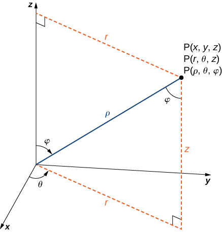
Spherical coordinates to rectangular coordinates We’ll now discuss how to go the opposite direction – from spherical to rectangular coordinates. Note the right triangle relationships in the following figure:

The sine of an angle is the length of the opposite leg, divided by the length of the hypotenuse: \(sin(\varphi) = \frac{r}{\rho}\). Therefore \(\rho \mbox{ sin } \varphi = r\).
At this point, we can consider only triangles inside the x-y plane. If \(r\) is the hypotenuse of a triangle in the x-y plane, then \(x = r \mbox{ cos } \theta\) and \(y = r \mbox{ sin } \theta\).
To compute \(z\), we can notice one more right triangle above, where \(\mbox{ cos } \varphi = \frac{z}{\rho}\), meaning \(z = \rho \mbox{ cos } \varphi\).
We have derived the following relationships:
- \(x = \rho \mbox{ sin } \varphi \mbox{ cos }\theta = r \mbox{ cos } \theta\).
- \(y = \rho \mbox{ sin } \varphi \mbox{ sin } \theta = r \mbox{ sin } \theta\).
- \(z = \rho \mbox{ cos } \varphi\).
We’ll now provide some simple code to do this, adapted from HoHoNet. Note that the image unwraps from left to right as the horizontal pixel coordinate \(u\) increases, so we negate \(u\) to obtain \(\theta\). Note that the vertical pixel coordinate \(v\) increases from top to bottom, whereas we want \(\phi\) to
def get_uni_sphere_xyz(H: int, W: int) -> np.ndarray:
    """Convert equirectangular pixel coords to 3d points in Cartesian space.

    First, convert equirectangular proj. pixel coordinates to spherical coordinates (theta, phi)
    on unit sphere. Then convert spherical coordinates to rectangular/cartesian coordinates.

    Adapted from HoHoNet: https://github.com/sunset1995/HoHoNet/blob/master/vis_depth.py#L7
    Note: The -x axis points towards the center pixel of the equirectangular projection.

    Args:
        H: integer representing height of equirectangular panorama image. An (H,W) grid will be created.
        W: integer representing width of equirectangular panorama image.

    Returns:
        sphere_xyz: array of shape (H,W,3) representing x,y,z coordinates on the unit sphere
            for each pixel location. Note that rho = 1 for all spherical coordinate points.
            Note that a spherical depth map (containing rho values) could be elementwise multiplied
            with the output of this function (rho is a constant multipler on each dimension below).
    """
    v, u = np.meshgrid(np.arange(H), np.arange(W), indexing="ij")
    # go through the center of the pixel (add 0.5) and account for image left to right unwrapping
    theta = -(u + 0.5) / W
    # scale theta to [0,2pi]
    theta *= 2 * np.pi
    # `v` is phi. go through the center of the pixel.
    phi = (v + 0.5) / H
    # scale to [-0.5,0.5]
    phi -= 0.5
    # scale to [0,pi]
    phi *= np.pi

    z = -np.sin(phi)
    r = np.cos(phi) # TODO: explain why this is not sin(phi)
    y = r * np.sin(theta)
    x = r * np.cos(theta)
    # stack three (H,W) maps into (H,W,3)
    sphere_xyz = np.stack([x, y, z], -1)
    return sphere_xyz
Below, we visualize the colored point cloud using Open3D, with Cartesian coordinates generated from the function above:


For an equirectangular projection, generally W=2*H in practice, since we have double the field of view along the horizontal direction compared to the vertical direction, e.g. (H,W) = (512,1024) or (1024,2048). Here, we consider the distance of a 3d point from the origin to be \(\rho=1\), and we let \(-u=\theta\). In the code above, not that we computed \(z\) as \(z=\rho \sin(v)\), instead of \(z=\rho \cos(\phi)\), as the equations above dictated. This follows because sine and cosine are cofunctions (Khan Academy notes here).


Recall that \(90^\circ\) is \(\pi/2\), and \(v \in [-\pi/2, \pi/2]\). We can see that if \(v\) is measured from the equator, then \(v + \varphi = \pi/2\), so by arithmetic, \(v=\pi/2 - \varphi\).
Now, by the cofunction identity:
\[\begin{aligned} \cos(\varphi) &= \sin(90^\circ - \phi) \\ \cos(\varphi) &= \sin(v) \end{aligned}\]Note finally that we took the negative sign, since negative angles \(v\) actually point upwards, and should have positive \(z\) values, therefore we can use the negative angle identity \(\sin(-x) = -\sin(x)\).
Recovering Perspective Images from a Panorama
Panoramic images (i.e. spherical images) have W=2H, and the focal length is \(W / 2 \pi\) pixels (See [2]).
We’re accostumed to (mostly) distortion free images from pinhole cameras. Choose image size, or choose fov, or choose focal length…
Jianxiong Xiao and his co-authors [1] introduced a popular codebase named pano2photo in 2011 as part of their work. Below, I port it from MATLAB to Python and describe the derivation of the spherical coordinate transformations. Others have ported the code to Python, including imgLookAt() and warpImageFast()` here and here.
People normally put the camera in a position that the top of the projection sphere is pointing to the sky [2]. A coordinate system is created such that \([-\frac{W}{2}, \frac{W}{2}] \times [-\frac{H}{2}, \frac{H}{2}]\)
Let \((x,y)\) be the image coordinate of a point \(\mathbf{P} = (X,Y,Z)\). If \(y\) is measured along the vertical axis in the spherical image plane, and \(x\) is measured along the horizontal axis, then \(\theta_y\) represents the pitch angle to \(\mathbf{P}\), and \(\theta_x\) represents the yaw angle to the same 3d point. In other words, \(\theta_y\) represents how much of \(180^\circ\) or \(\pi\) radians we must rotate to send a ray out to \(\mathbf{P}\) from the sphere’s origin. This value is proportional to how high or low \(y\) is in the equirectangular image, i.e. \(\theta_y = \pi \cdot \frac{y}{H}\).
Likewise, our yaw angle is determined by how far around \(360^\circ\) or \(2 \pi\) radians the image coordinate \(x\) is located along the horizontal axis, i.e. \(\theta_x = 2 \pi \cdot \frac{x}{W}\).
Tangent Images
Marc Eder, Spherical-Package
E2P Transformation (Equirectangular Panorama to Perspective Image)
Modern room layout estimation networks like DuLa-Net [3] use the “E2P” transformation to differentiably transform a perspective image coordinate to a panorama image coordinate.
As described in Section 4 of the DuLa-Net paper, assumes we are dealing with a square perspective image of dimension \(w \times w\). For every pixel in the perspective image at position \((p_x,p_y)\), we derive the position of the corresponding pixel in the equirectangular panorama, \((p_x^\prime, p_y^\prime)\), \(-1 \leq p_x^\prime \leq 1\), \(-1 \leq p_y^\prime \leq 1\), as follows. We define the field of view of the pinhole camera of the perspective image as \(\theta_{FOV}\). Then, the focal length can be derived as

Now, \((p_x,p_y,f)\), the 3d position of the pixel in the perspective image in the camera space, is then rotated by \(90^\circ\) or \(-90^\circ\) along the x-axis (counter-clockwise, i.e. by right-hand rule) if the camera is looking upward (e.g. looking at the ceiling) or downward (looking at the floor), respectively.
Next, we project the rotated 3d position to the equirectangular space. To do so, we first project it onto a unit sphere by vector normalization, i.e.
\[\begin{bmatrix} s_x & s_y & s_z \end{bmatrix}^T = \frac{\begin{bmatrix} p_x & p_y & f \end{bmatrix}^T } { \| \begin{bmatrix} p_x & p_y & f \end{bmatrix}^T \|_2 }\]Afterwards, we can find \((\theta, \varphi)\) which determine the distance we must travel along the horizontal and vertical axes to arrive at a equirectangular coordinate. We wish to estimate \(\theta\) and \(\varphi\) below, given rectangular coordinates:

We see: \(\mbox{tan}_2 (\theta) = \frac{s_x}{s_z}\)
\[\theta = \mbox{tan}_2^{-1} \frac{s_x}{s_z}\] \[\frac{s_y}{1} = \mbox{sin} \varphi\] \[\varphi = \mbox{sin}^{-1}(s_y)\] \[(p_x^\prime, p_y^\prime) = \Bigg( \frac{\theta}{\pi}, \frac{\varphi}{0.5\pi} \Bigg)\]Recovering 3D Structure from Panorama
For highly-structured environments like the indoors of residential spaces, a detected layout boundary in a panorama is easily translated into 3d structure, if camera height is known. Papers like Extreme SfM use a pretrained layout estimation network like HorizonNet to estimate a boundary in a top-down view. The scale comes from the assumption that the camera height is a known amount of meters above a ground plane.
Datasets with Panoramas
- Matterport3D Data, Paper
- MatterportLayout: (uses panoramas from Matterport3D) Data, Paper
- Zillow Indoor Dataset (ZinD): Data, Paper
References
[1] J. Xiao, K. Ehinger, A. Oliva, and A. Torralba. Recognizing scene viewpoint using panoramic place representation. In CVPR, 2012.
[2] Jianxiong Xiao. 3D Geometry for Panorama. Massachusetts Institute of Technology. PDF.
[3] Shang-Ta Yang, Fu-En Wang, Chi-Han Peng, Peter Wonka, Min Sun, Hung-Kuo Chu. DuLa-Net: A Dual-Projection Network for Estimating Room Layouts from a Single RGB Panorama. CVPR 2019. PDF.